24GHz MIMO Radar Module Eval Kit
MIMO Radar module with Analog Devices ADF5901/ADF5904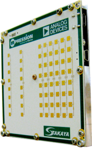
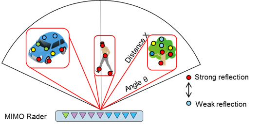
24GHz MIMO Radar module Evaluation Kit is a MIMO Radar module with Analog Devices MMICs ADF5901 24 GHz VCO and PGA with 2-Channel PA Output and ADF5904 4-Channel 24 GHz Receiver Downconverter. MIMO (Multi Input Multi Output) array antenna technology used in this module enables long-distance and wide-range azimuth detection, virtually increasing the number of Rx elements and improve the azimuth resolution.
Macnica's partner Sharp Takaya provides its signal processing technology for this module, enabling accurate detection of the angle and distance of the reflected wave and displaying the point with signal strength.
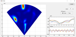
The derived signal data can be used to recognize objects such as people, cars, obstacles, etc. A sample radar display application software is included in the kit to show the strength of signals in a "heatmap" style scope.
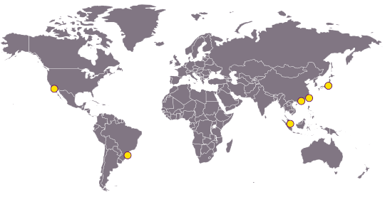
24 GHz spectrum is an ISM band widely used for radar applications in many countries.
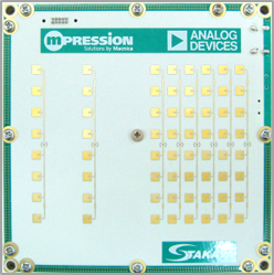
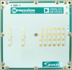
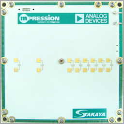
Macnica offers 6 different types of MIMO configurations for this module kit to meet various customer requirements.
Specifications
- Module Size:100(W)mm x 100(D)mm x 7.5(H)mm
- Interface:USB2.0(UART), USB3.0(Power)
- Power supply:5.0V
- Current consumption:0.7A
- Frequency:24.05~24.25GHZ
- Modulation bandwidth:190 MHz
- Measurement distance range (Typ.) : 0.75~105m
- Angle distance range (Typ.):±40deg
- Chirp time:260us
Feature
- High precision and miniaturization achieved by ADI’s MMIC and Sharp Takaya's signal processing technology
- MIMO technology enables detection with a wide range of azimuth over a long distance
- Detection of body movement and vibration is also possible
- 24 GHz used in many countries
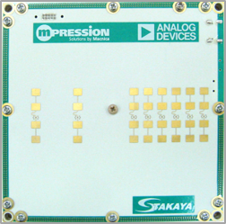
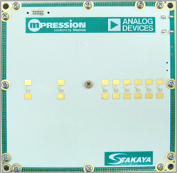
6 types of MIMO configurations
| Antenna Type | 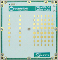
|
|
|
|
|
|
|
|---|---|---|---|---|---|---|---|
| Transceiver (Tx) | Patch | 1x8 | 1x4 | 1x2 | 1x8 | 1x4 | 1x2 |
| Receiver (Rx) |
Patch |
1x8 | 1x4 | 1x2 | 1x8 | 1x4 | 1x2 |
| Transmit antenna half-angle (Typ.) |
Azimuth (deg) | +/- 40 | +/- 40 | +/- 40 | +/- 70 | +/- 70 | +/- 70 |
| Elevation (deg) | +/- 7 | +/- 10 | +/- 20 | +/- 7 | +/- 10 | +/- 20 | |
| Receiving antenna half-angle (Typ.) |
Azimuth (deg) | +/- 40 | +/- 40 | +/- 40 | +/- 70 | +/- 70 | +/- 70 |
| Elevation (deg) | +/- 7 | +/- 10 | +/- 20 | +/- 7 | +/- 10 | +/- 20 | |
| Polarization direction | Vertical | Vertical | Vertical | Horizontal | Horizontal | Horizontal | |
| Output power (Typ.) | dBm EIRP | 20 | 18.5 | 16 | 18.5 | 15 | 12 |
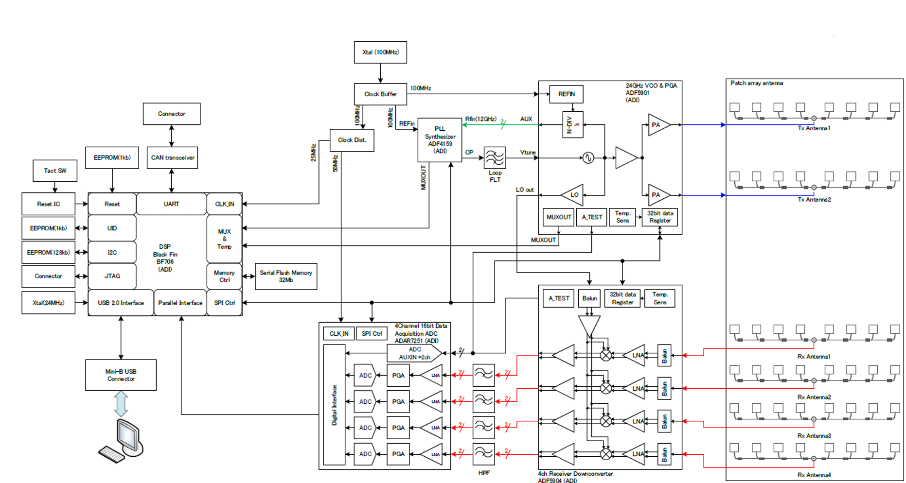
Circuit Configurations
Devices Used:
- ADF5901:24 GHz VCO and PGA with 2-Channel PA Output
- ADF5904:4-Channel, 24 GHz, Receiver Downconverter
- ADF4159:13 GHz, Fractional-N Frequency Synthesizer
- ADAR7251:4-Channel, 16-Bit, Continuous Time Data Acquisition ADC
- ADSP-BF706:Low Power 400MHz Blackfin+ Embedded Processor with 1MByte L2 SRAM
- ADP5024:Dual 3 MHz, 1200 mA Buck Regulators with One 300 mA LDO
- ADM7172:6.5 V, 2 A, Ultralow Noise, High PSRR, Fast Transient Response CMOS LDO
Schematics: