
Odyssey Personality - ADC & Audio Monitor
Introduction
This personality allows the user to read the value of the Max10 FPGA Analog to digital convert channels. The Odyssey Max10 FPGA board also reads the microphone and outputs the sound level on the LEDs.
How To Use
Tap the board close to the microphone to see the sound level bars displayed on the LEDs. The microphone is located to the right of the Max10 FPGA device, under the micro-USB connector if the Bluetooth board is attached.
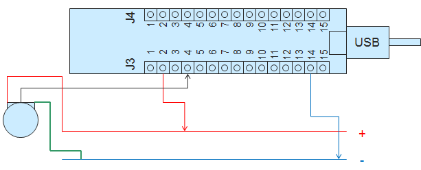
Six ADC channels are also brought out to pins on the Max10 board. The app allows you to read the voltage on five of these pins. To vary the voltage, connect a potentiometer between 3.3V and ground and run the variable leg to one of the pins. Adjust the potentiometer and read the voltage on the app. J3 pins 4-9 are the ADC inputs.
How It Works
The Max10 devices contain up to two 12-bit, 1MSPS SAR analog to digital converters with up to 18 analog inputs total. There is also a temperature sensing diode and a prescaler on each ADC. A reference voltage can be provided or generated internally.
Altera provides IP that can create complex scheduled sampling of the different inputs channels. This personality enables all the channels and samples each in a round-robin style. App buttons are provided to turn the sampling on or off.
The microphone is sampled and maximum value each 0.1 seconds is translated to a level that is displayed on the LEDs. The other channels are scaled to a multiple of 1mV and written to registers so they can be read by the phone app. Like all communication between the phone app and MAX 10 FPGA, the values are communicated via I2C-compatible commands from the Broadcom Bluetooth module.
More Info
- Altera Reference Design Store [click here]
- Altera MAX 10 FPGA product info [click here]
- All Odyssey Kit Downloads [click here]