
Odyssey Personality - Frequency Detection
Introduction
This personality uses the Max10 PLL to generate several output frequencies based on the input oscillator. It also has a frequency counter used to measure a generated clock or an external clock. LEDs output a binary representation of the detected frequency in 0.1Mhz increments.
How To Use
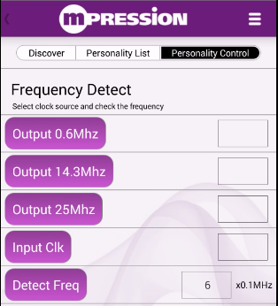
After connecting the Odyssey board with your smartphone app, select the Frequency Detect personality. Use the buttons to select either 0.6MHz, 14.3MHz, 25MHz, or the input pin as the source to the frequency detector. Use the Freq Detect button to measure the selected clock.
The external frequency detector input comes in on the Max10 board connector (DIP pin) J4 pin 3. An external frequency between 0.1Mhz and 25Mhz can be provided to that pin and read via the freq detect button on the App. J4 pin 5, pin 7, and pin 9 output the clocks generated by the Max10 PLL, and these can be externally fed into the frequency detector input as a test. J4 pin 15 also mirrors the clock selected by the frequency detector.
How It Works
The Max10 family includes FPGAs with up to four high-performance integer mode PLLs. The Odyssey Max10 FPGA Evaluation Kit provides a 50Mhz clock to the Max10 using a Silicon Labs MEMS oscillator. The Max10 PLL then multiplies up the frequency internally, then uses divider counters to create multiple outputs.
The frequency detector works by using a fourth PLL output at 100MHz, then counting how many of these 100MHz clock periods occur between the rising edges of the sampled clock. An arithmetic divider is then used to output the result in 0.1MHz increments. It's accurate to within about 0.1MHz.
More Info
- Silicon Labs' MEMS Oscillator Products [click here]
- Altera Reference Design Store [click here]
- Altera MAX 10 FPGA product info [click here]
- All Odyssey Kit Downloads [click here]